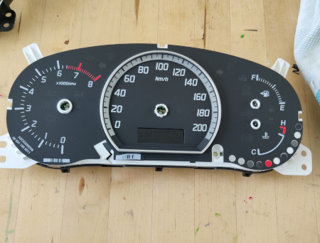
Suzuki Swift instrument cluster backlight repair, step by step. European Swift from 2009. Type MZC21 (MZC21S).
Introduction
From: 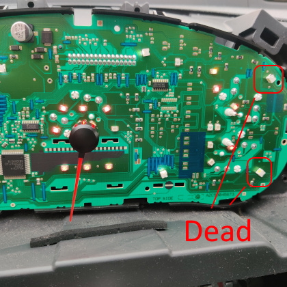
To: 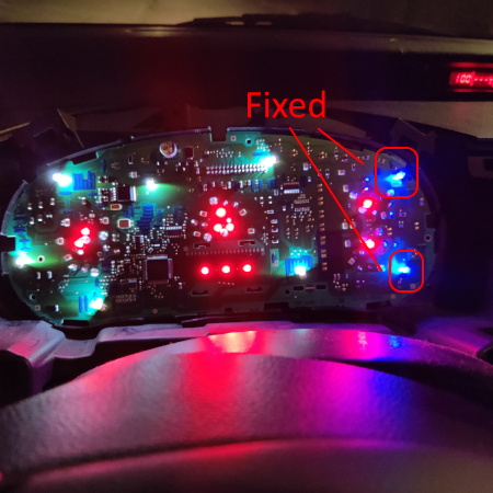
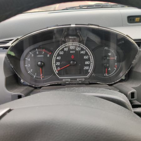
In November 2022 the instrument cluster backlight of our 2009 Swift started dying. Two LED’s completely failed, another one was flickering.
The dealer indicated repairing the instrument cluster wasn’t something they do. It would have to be shipped to another company in order for it to be repaired. The dealer did tell me removing the instrument cluster was easy, hence I decided to have a go at doing the repair myself.
Here’s the step by step log.
Steps
Tools and parts used
- Philips screwdriver
- Small flathead screwdriver
- Tongs
- Cloth
- Spanner (to disconnect the battery)
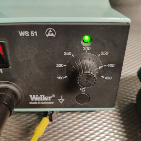
- Soldering iron (400°C, tip 0.75 ~ 1.00mm)
- Tweezers
- 8x cube SMT LEDs, I used OSRAM LB A673-M2P1-35
Steps
- Disconnect the negative pole from the battery.
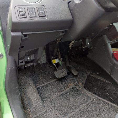
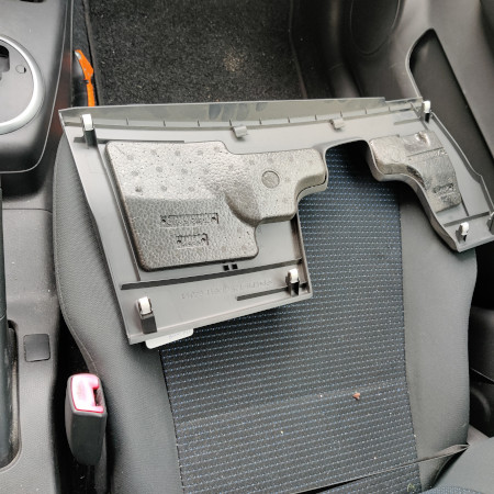
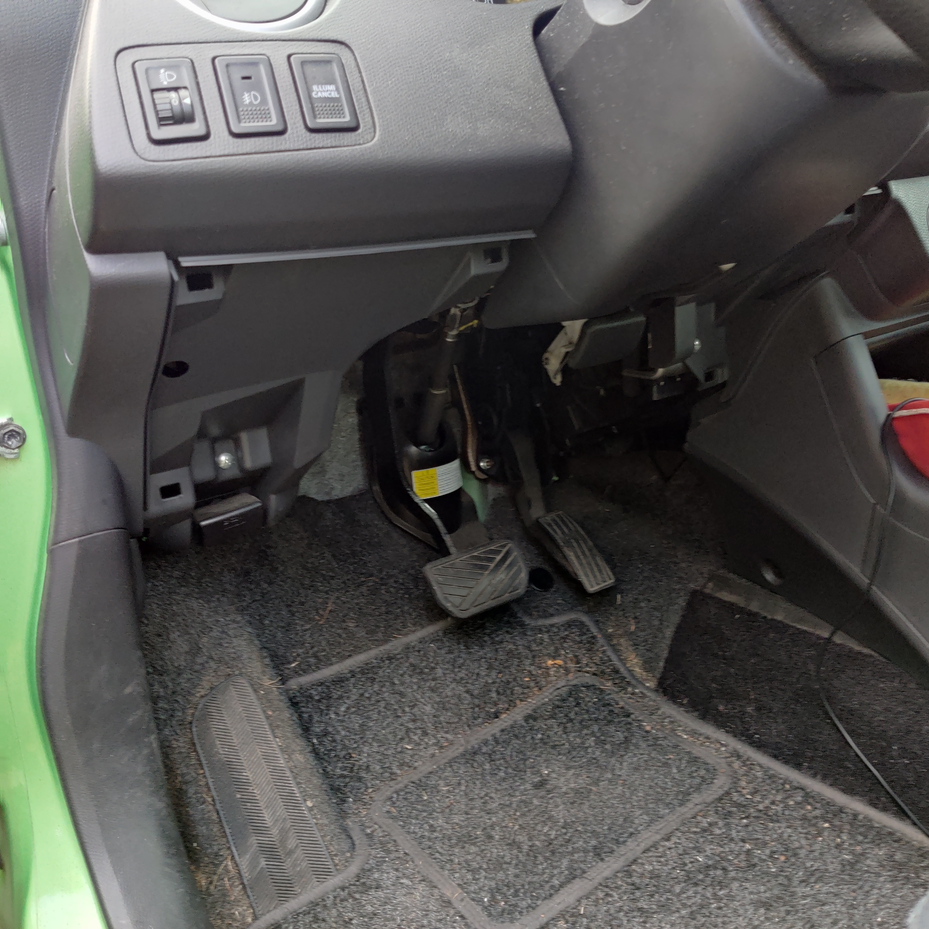
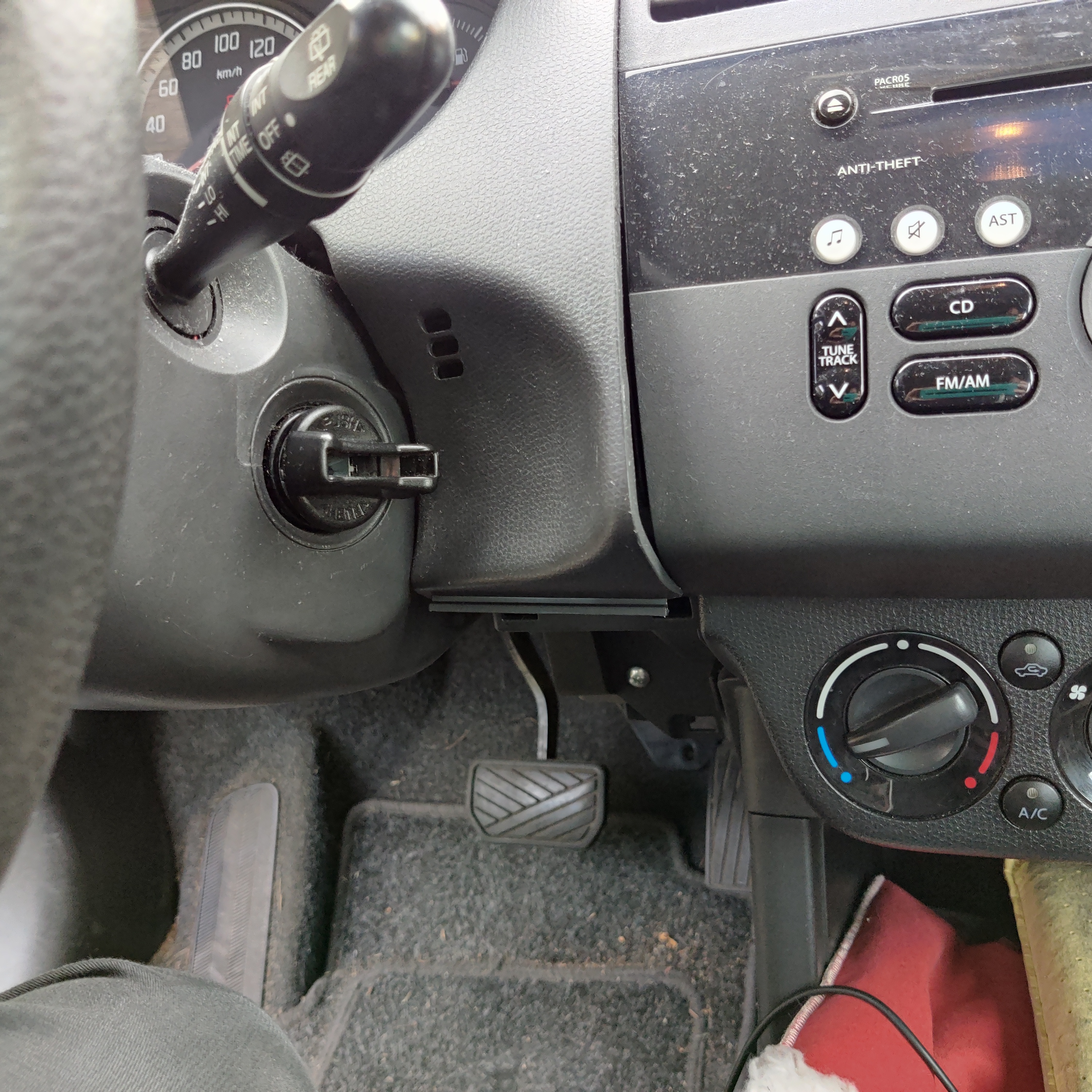
- Remove the lower panel by pulling it towards you at the bottom. The panel is held in place by four plugs which snap in and out of position.
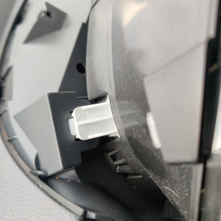
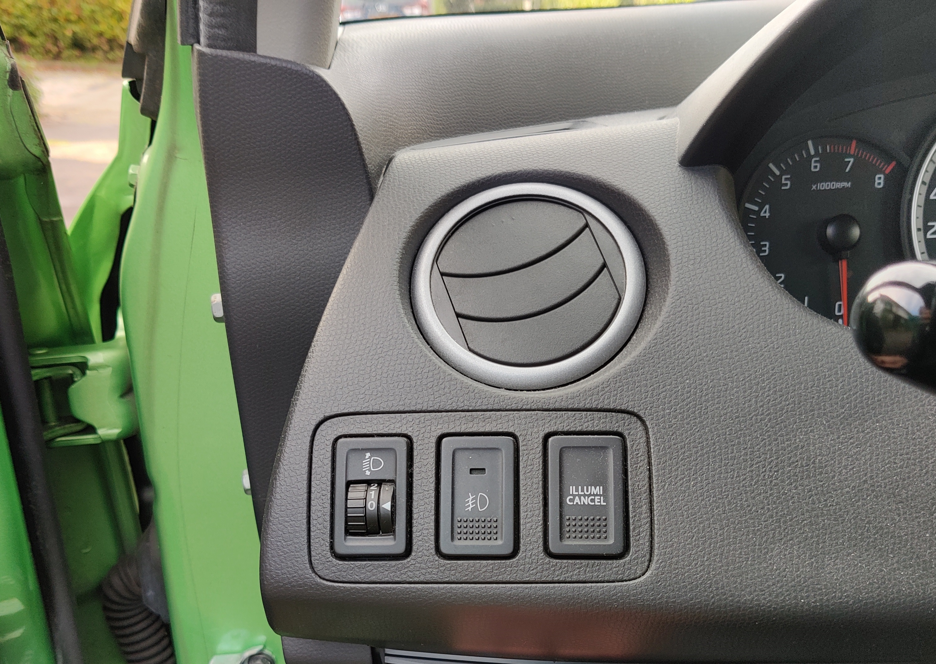
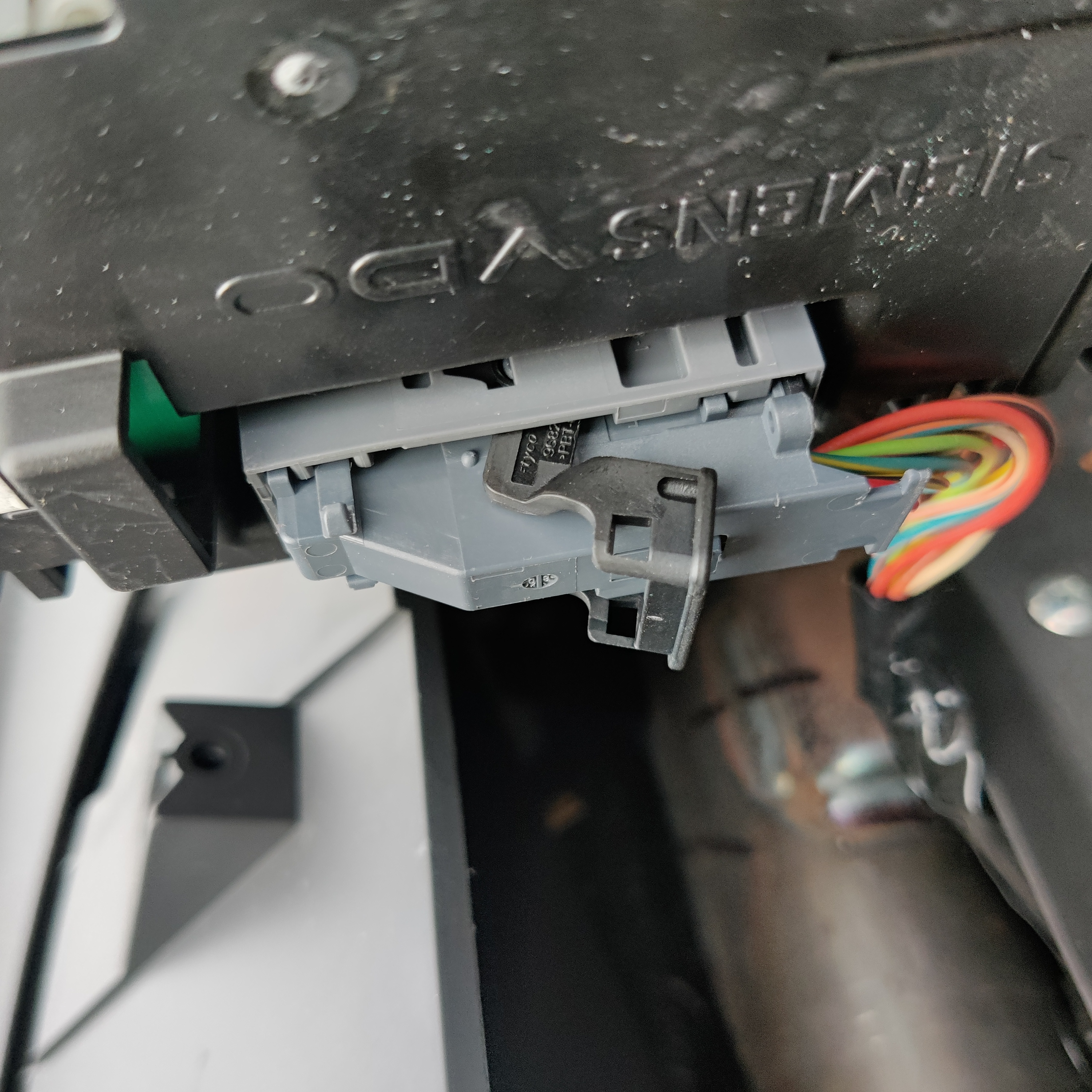
- Do the same for the panel covering the instrument cluster. There are three buttons on the left. Disconnect their electrical connectors on the back of the panel. They are color coded, which is practical when re-connecting them. Make sure they don’t fall “into” the car (towards the engine).


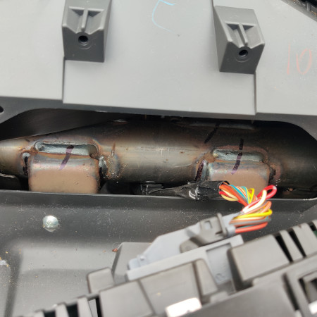
- Remove the two screws holding the instrument panel in place.
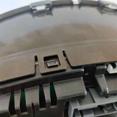
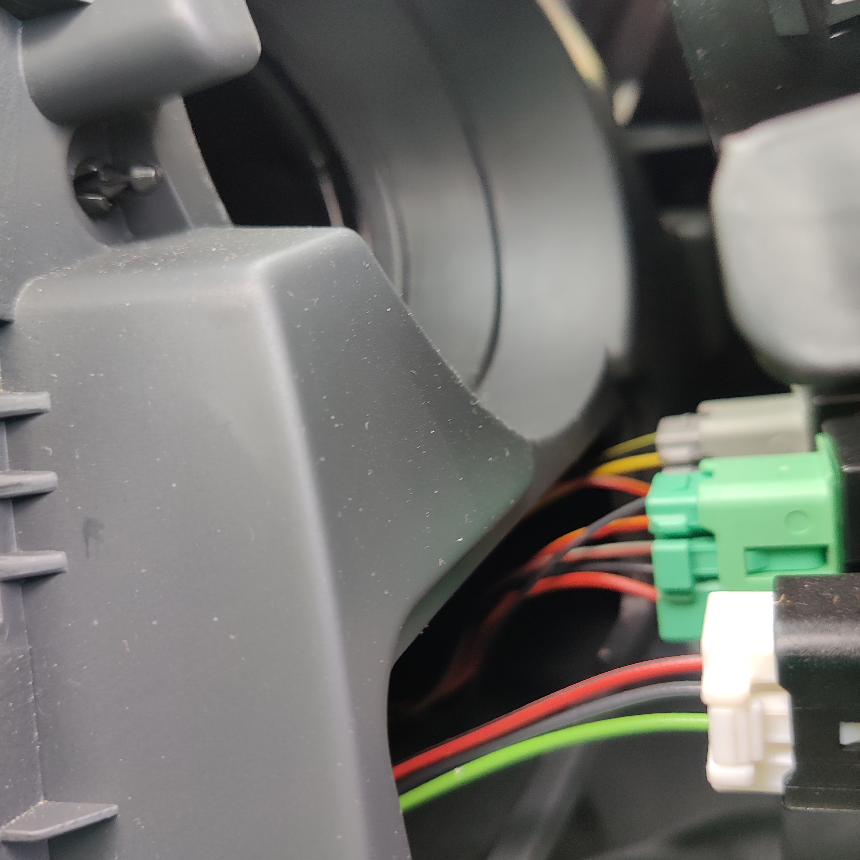
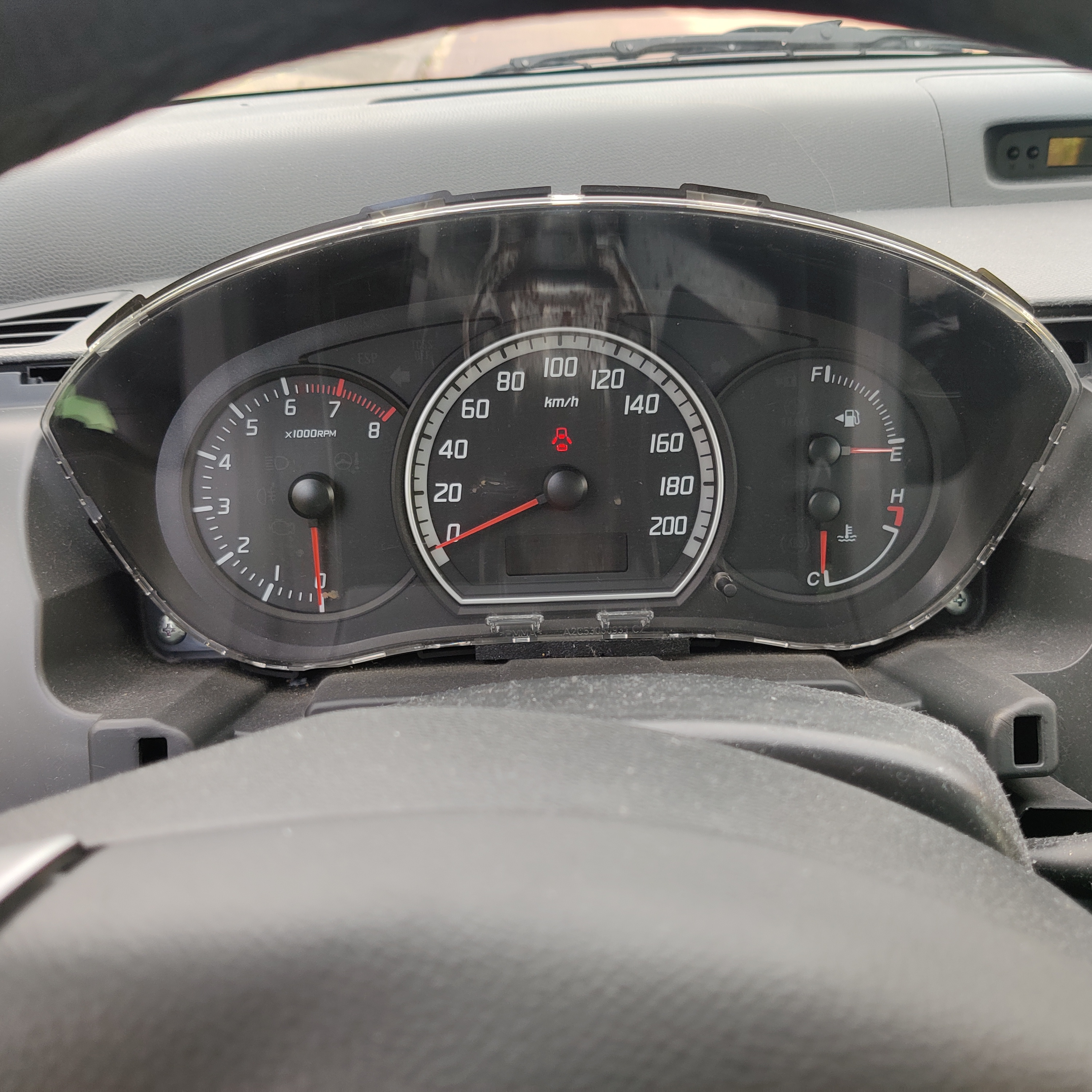
- Pull the instrument panel forward, releasing the two snap connectors on the top.
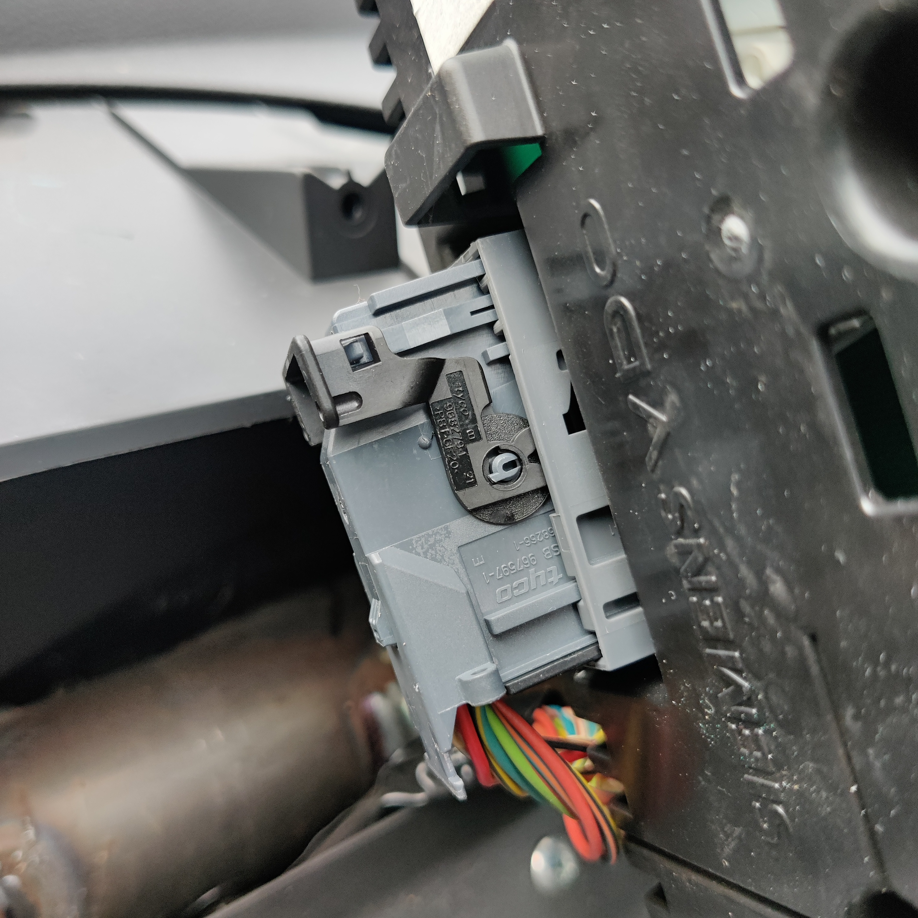
- The connector on the back of the instrument panel is moved in and out of position by a lever. Release the lever.
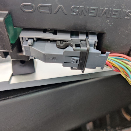


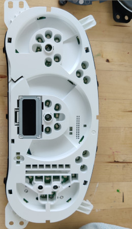
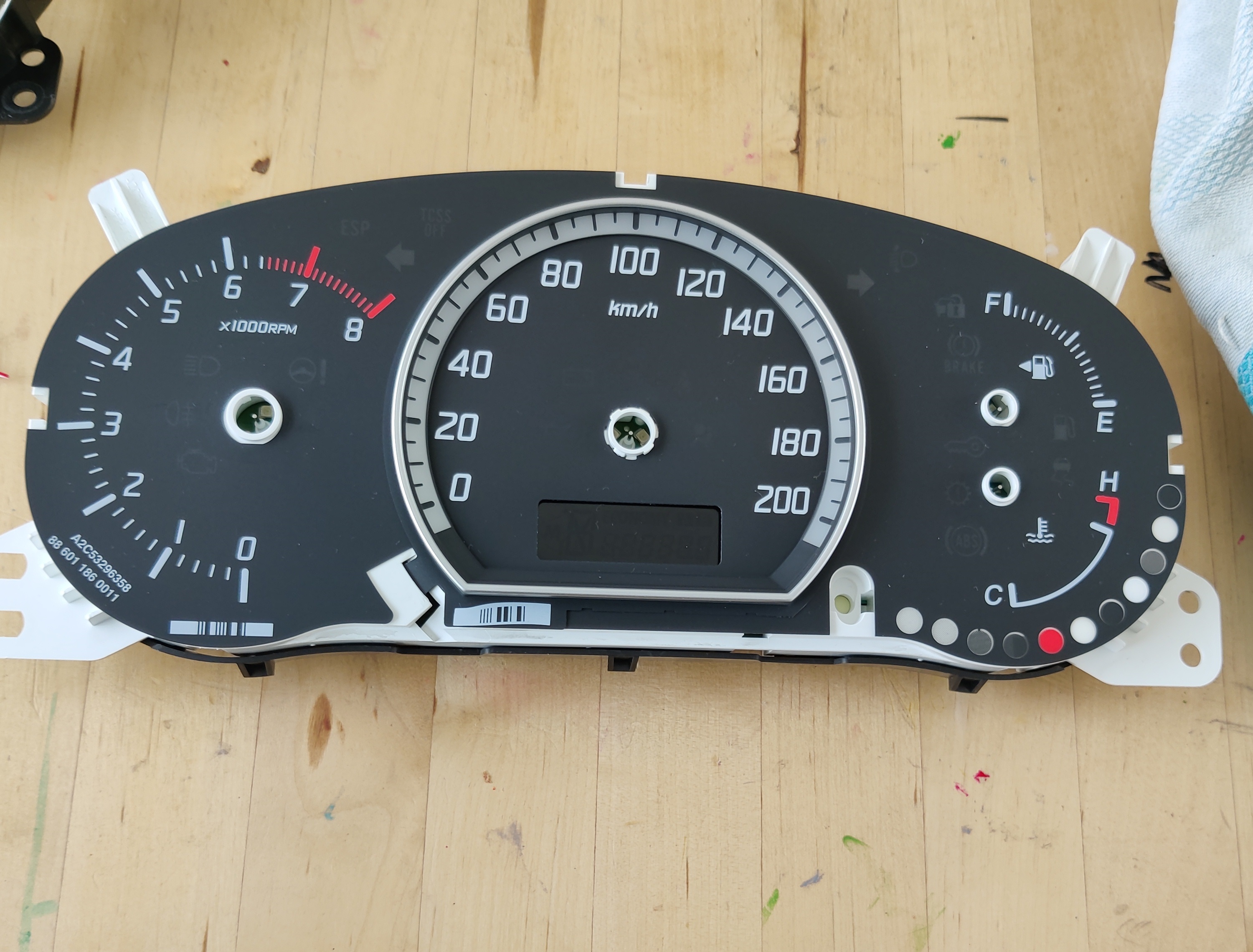
- The instrument cluster is now out. The front part of the instrument cluster is held in place by snap connectors. Release them.
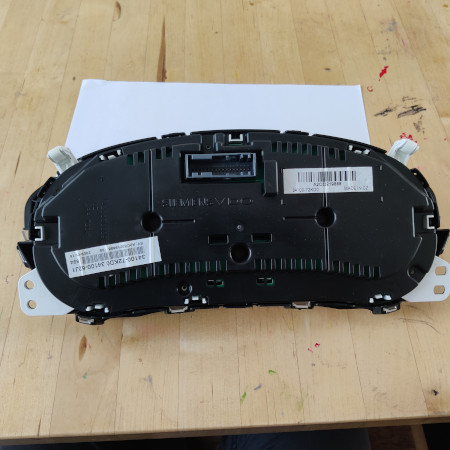
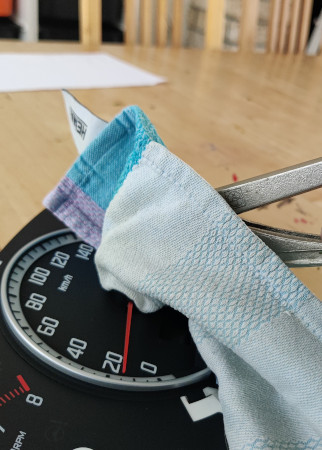
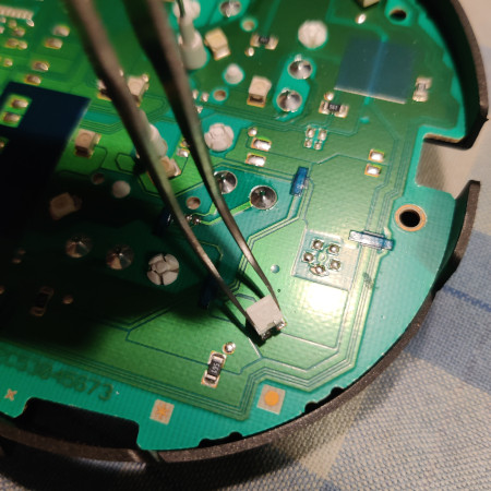
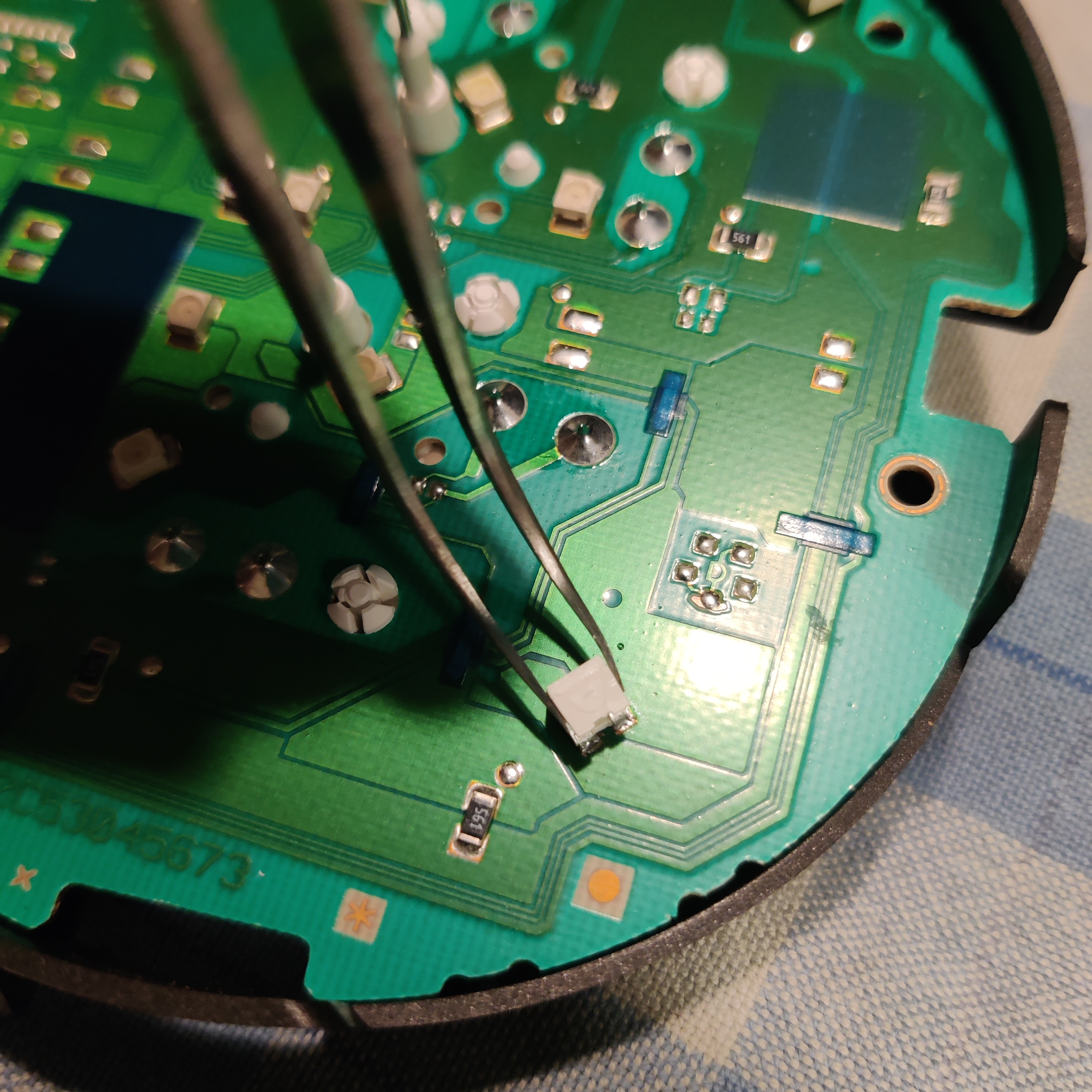
- Remove the needles by pulling them of the motor shafts. I used a tong with a cloth to prevent scratches on the plastic.
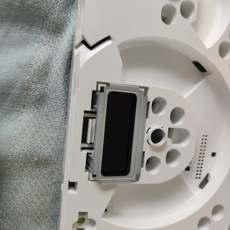
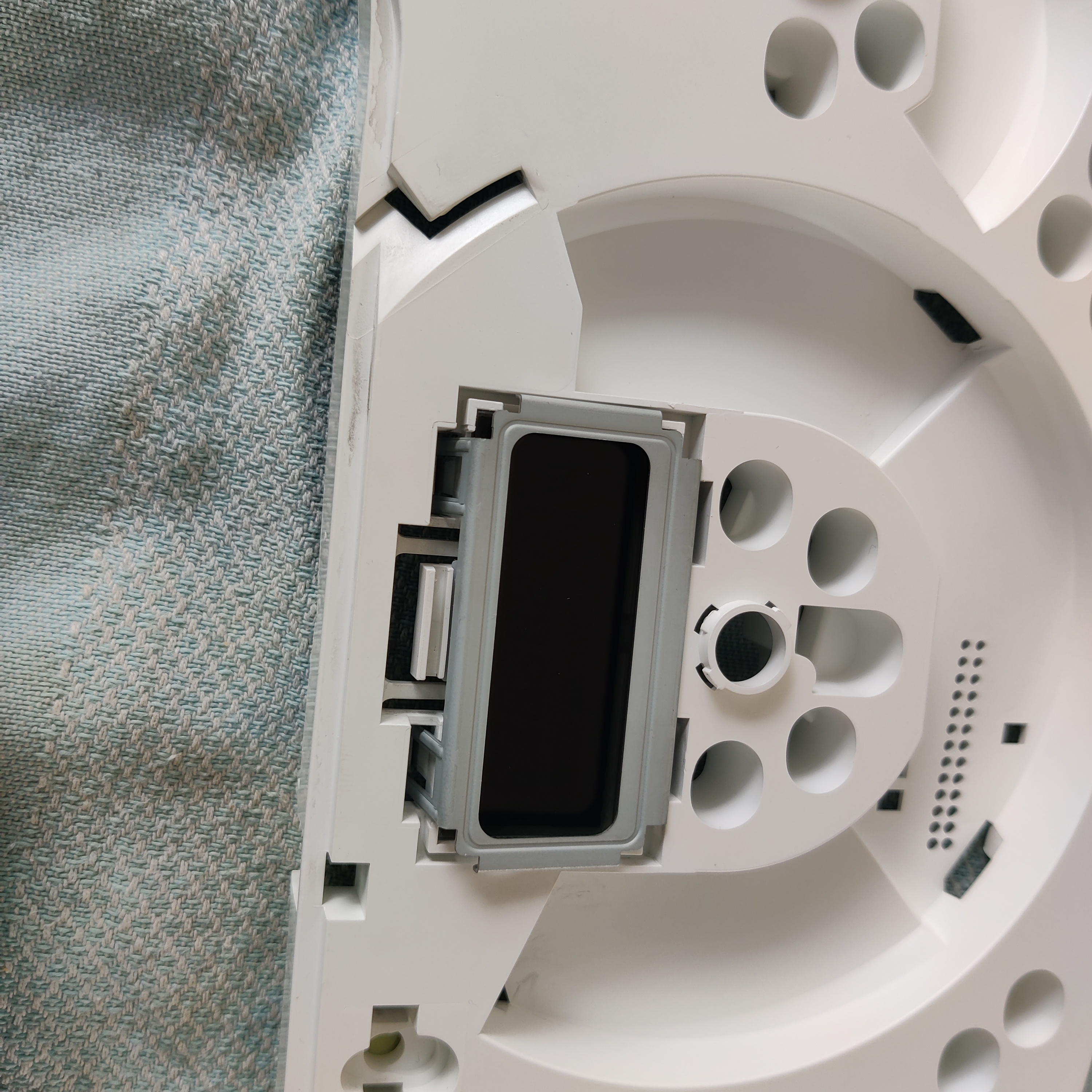
- Remove the plastic sheets which make up the visible part of the instrument cluster.
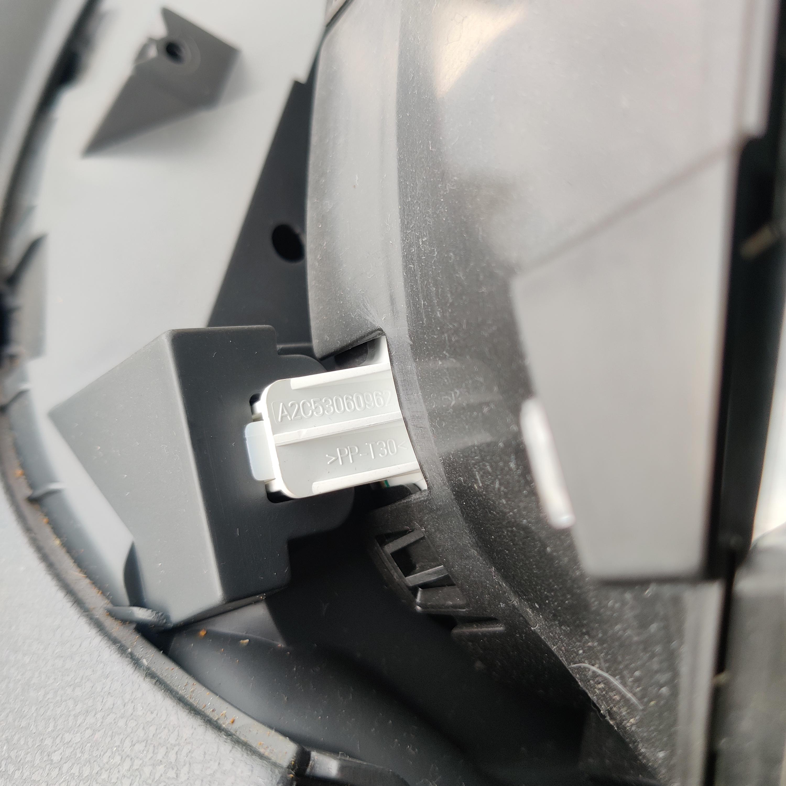
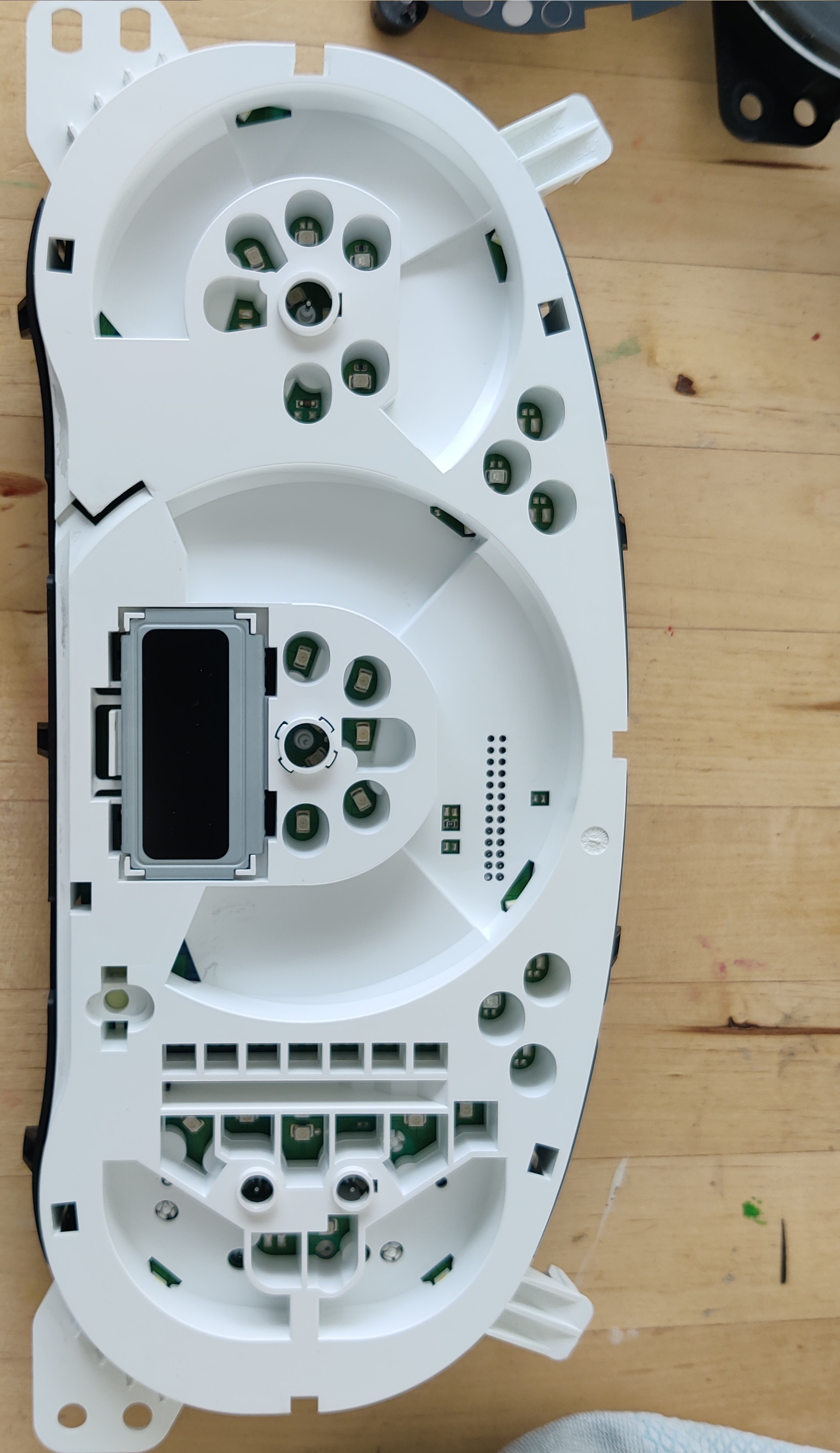
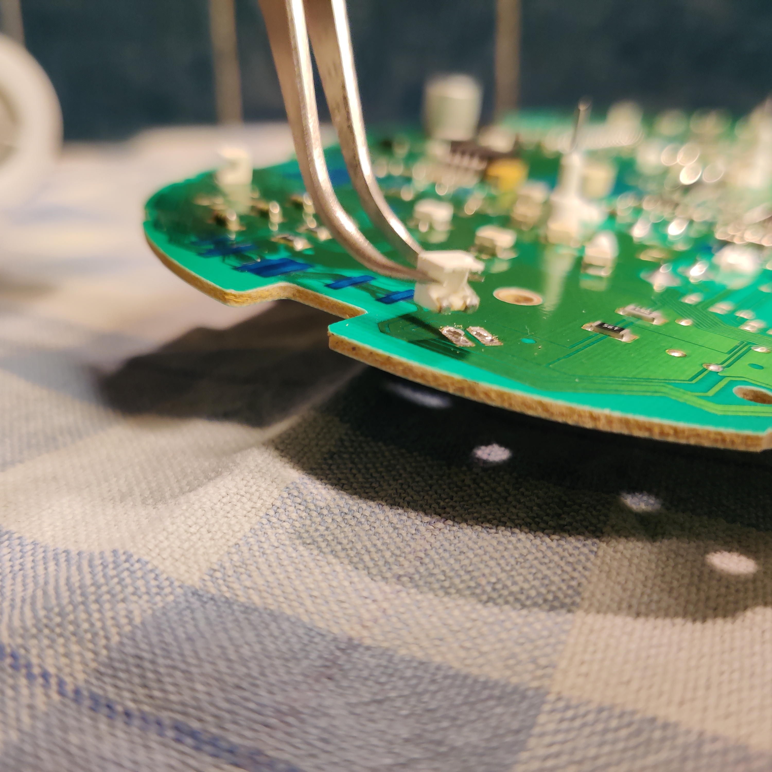
- Detach the four snap connectors of the metal bracket which firmly links the display to the PCB. I was unable to completely remove the metal bracket, but this wasn’t needed.
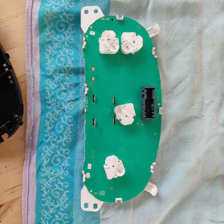
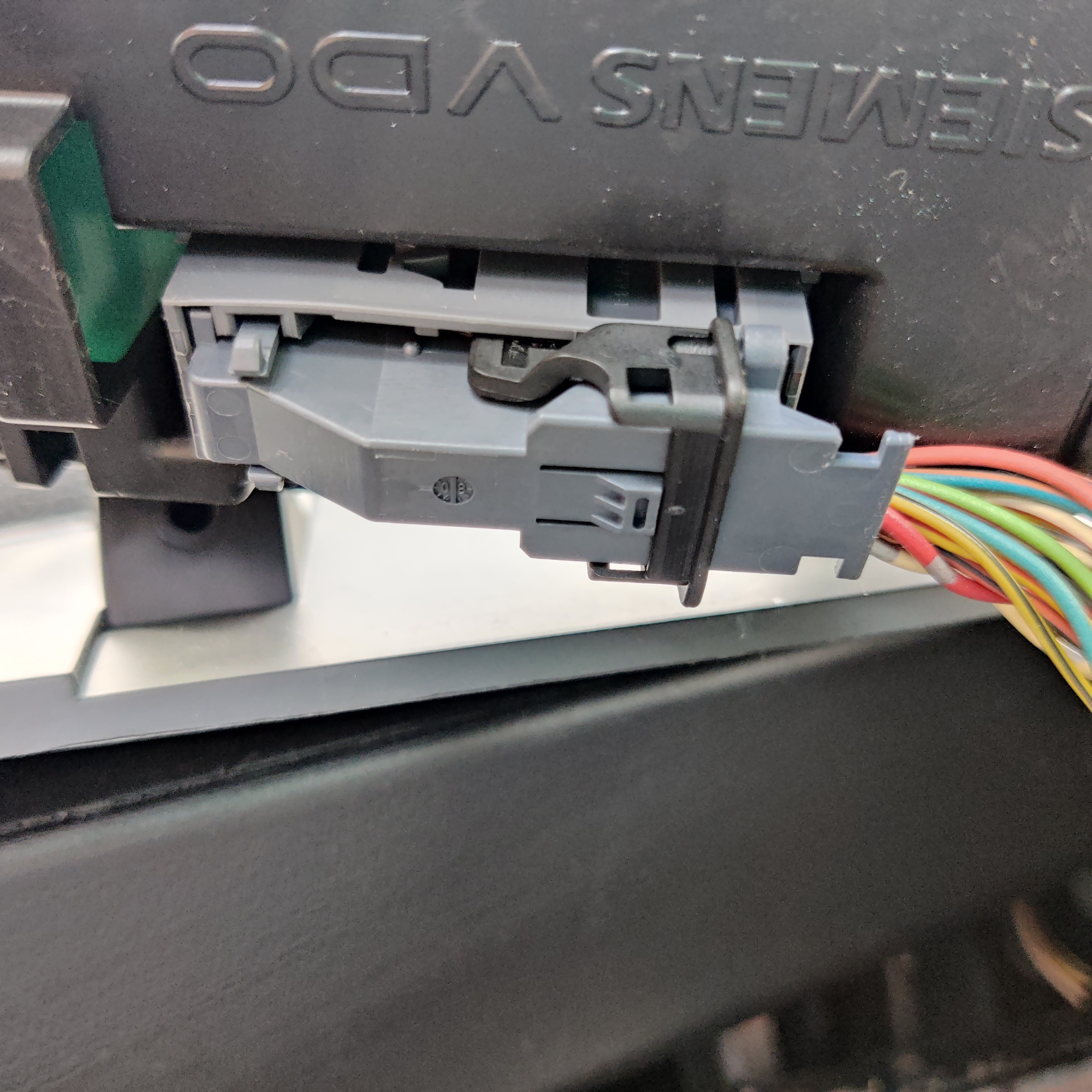
- Release the white plastic snap connectors which connect the PCB to the big white plastic part. The PCB will now come off. Make sure you work EDS safe when handling the PCB.
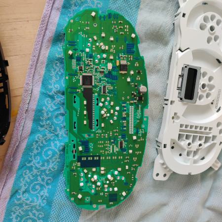
- I re-installed the PCB at this point to verify that the LEDs where indeed dead, and to measure the voltage across the LEDs. I measured:


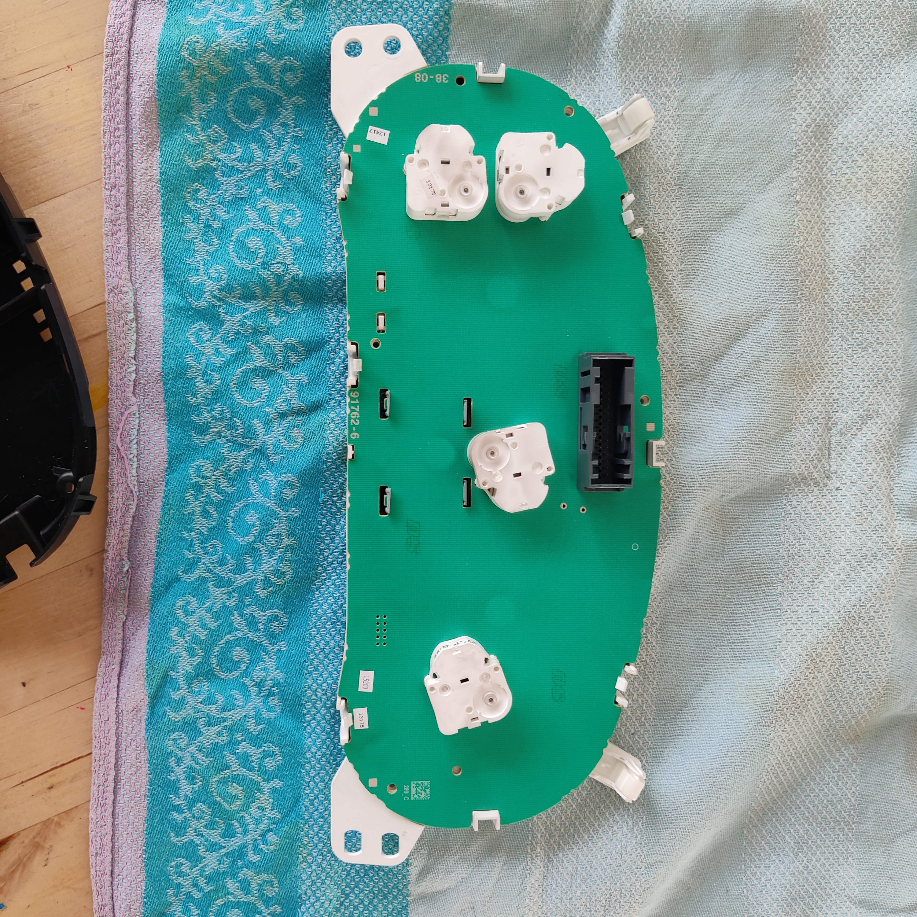
- 8.4v when measuring both dead LEDs on the right (gasoline and motor temperature indicator), they are connected in series.
- 2,4v measuring the functioning LED for the left part of the speed indicator.
- This is also a good moment to reset the location any of the arrow motors to zero. I rotated the arrows when pulling them off as it’s very hard not to, meaning the needles would be in the wrong position after re-inserting them. Fortunately the motors reset to the 0 position when contact is enaged, so installing the PCB intro the car and engaging contact once solved this problem.
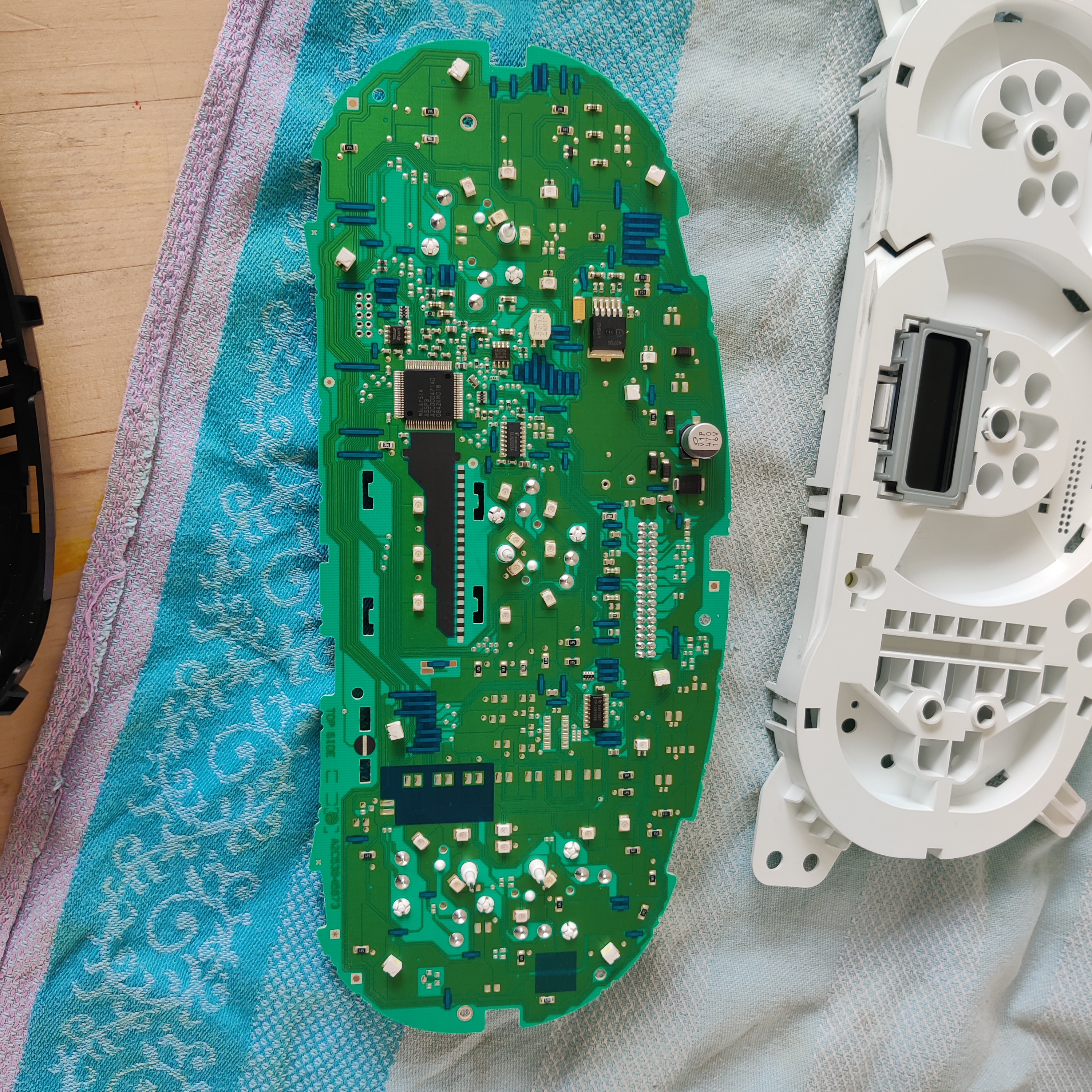
- To remove the LEDs I had to set the soldering iron to 400°C. I could heat only one of the two metal strips at a time, but discovered there’s some play in the LED package (read: housing). By applying a gentle force on the LED with the pliers while alternating between heating on or the other metal strip I was able to remove the LEDs without damaging the PCB.
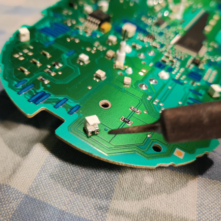
I add just a little bit of tin on the pads, and then soldered the new LEDs in place.

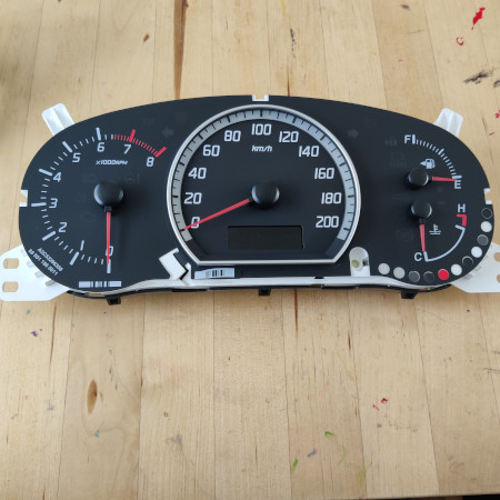
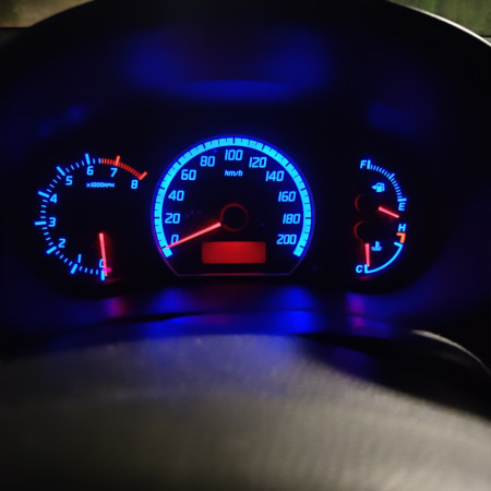
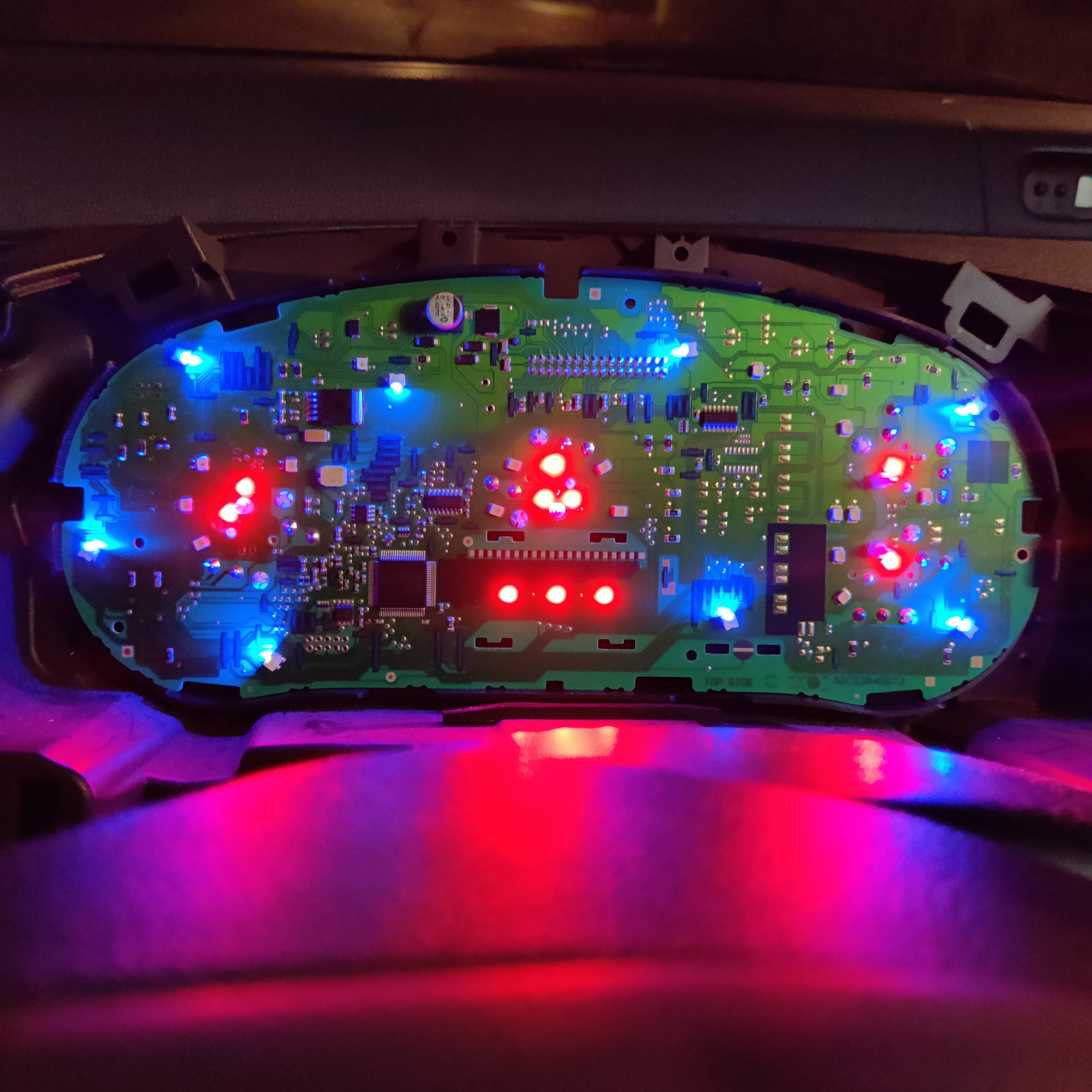
- After re-assembly the instrument cluster is nice lit again. It’s lit in blue now, blue is what I could order for this SMT form factor. The color serves as a nice reminder to this DIY repair 😎


History
2022-11-13 - Original blogpost